Details
Official Xbox Spider GX
The SpiderGX is the latest universally solderless Xbox chip from the talented SpiderChip Team. The SpiderGX is a clear step ahead of the previous generation of solderless Xbox Chips. This chip offers the best all round package for your Xbox modding needs, not only is it fully solderless on any Xb…
Retail: $ 79.95
$ 59.95 (� 45.20) Save 25%
We will have the new 1.1 in stock on Monday, Dec. 28th, and they will ship then. The issue on the 1.6B has been addressed as well as wire adjustments.
This is the new completely solderless SPIDERCHIP:
Install Tutorial Link: http://www.modchipstore.com/support/index.php?_a=knowledgebase&_j=rate&_i=42&type=yes&PHPSESSID=9e329001057887ce98c358c0aa28daa2
>
See details
Official Xbox SpiderChip Solderless Modchip
Official SpiderChip ! This Brand new Completely SolderLess Chip is compatible with ALL XBox’s to date. First Solderless chip to work on New Xbox Version 1.6. Nevertheless Spider chip is produced with the highest standards of quality, and comes inside a metal box to ensure safe delivery
Xecuter 3 CE and Xecuter 2.6 CE are expected to be back in stock on Dec. 7-8 {Wednesday or Thursday} and will resume shipping to customers then. Sorry for the delay!!
![]()
Xecuter 3 CE ModChip w/ 1.6 PCB. Works on ALL versions of Xbox!!
New Xecuter 3 CE is such a leap in its 5th generation upgrade. The only device is capable of on the fly bios configuration and more. This chip does everything, can allow you to boot games from HDD or Discs as well as store music, videos and just makes your Xbox a PC with Linux. New features include

Official Xecuter 2.6 CE ModChip. Works with ALL Xbox Versions 1.0-1.6b!
Official Xecuter 2.6 CE – Now works with all models including the latest v1.6 models. It also comes with the external switch as standard and cool blue LEDs. One of the world’s best Xbox mod chips on the market. The Xecuter 2.6 modchip allows the user to play import and backup games on their XBOX
Xbox™ Disassembly Instructions
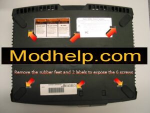
Step 1: Remove the 4 rubber pads and the 2 stickers where the arrows are pointing.

Step 2: Remove the 6 exposed to screws using a T15 Torx bit or screwdriver.

Step 3: Flip the console right side up and then carefully remove the cover.

Step 4: Remove the IDE(grey ribbon) cable from the Hard Drive and DVD Drive.

Step 5: This is a picture showing the ribbon cable removed from the DVD Drive.

Step 6: Remove the yellow power cable from the DVD Drive.

Step 7: Remove the power cable from the Hard Drive.

Step 8: Use a T10 Torx bit or screwdriver to remove the 3 screws. For a close-up of the screws please click the appropriate arrow.

Step 9: Remove the yellow power cable, the IDE(grey ribbon) cable, and the cooling fan connection.

Step 10: Remove the main power cable.

Step 11: Remove the front panel data cable (yellow cable for the Eject and Power button).

Step 12: Carefully remove the Controller port daughterboard.

Step 13: Using a T10 Torx bit or screwdriver removes the 11 screws. Once all 11 screws have been removed carefully remove the motherboard from the case.

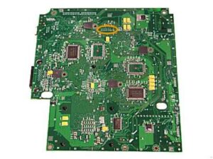
Step 14: This picture displays the case with only the power supply and cooling fan. The motherboard has been removed.

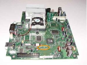
Step 15: This is the back of the motherboard. The red square indicates the installation location of the mod-chip.
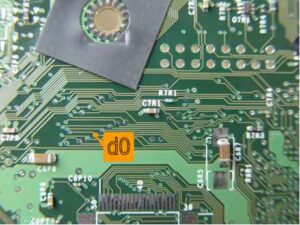
Locating the LPC port and d0 point.
The following picture shows the location of the LPC port on the top
side of the motherboard.
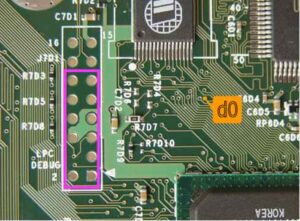
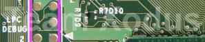
The picture below shows the location of the LPC port on the underside
of the motherboard.
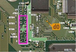
Version 1.0 motherboards have solder in the LPC port whereas later
versions do not as shown in the picture below. The pink rectangle in
these pictures indicates the area of the LPC that is used by the Xenium.
You also need to locate the d0 point on your motherboard, there is
a d0 point located on both the top and bottom of the motherboard.
The location of the upper d0 point will differ for motherboard versions
1.0-1.2 and 1.3-1.5. The underside (and slightly larger) d0 point is
the same for all motherboard revisions. Either the upper or underside
d0 is needed for the installation of the Xenium, Team Xodus recommends
the underside d0 point for those who have limited soldering skills.
Upper d0 point on Version 1.0, 1.1, and 1.2 Motherboard.
Upper d0 point on Version 1.3, 1.4, and 1.5 Motherboard
Underside d0 point on all Version Motherboards.
Disclaimer
By purchasing a Xenium you agree that the usage of this product is
strictly your responsibility. Team Xodus is not responsible for any
damage or loss of data caused during the installation or use of the
Xenium.
The Xenium is designed for use as a development tool and is shipped
with blank bios banks so that the end-user can install their own
bios. The developers of the Xenium are aware that various hacked
bios versions are available that contain copyrighted Microsoft code
and can be used for piracy and in no way do we endorse or condone
the use of such biases. Our primary purpose for the development of
this device is to encourage users to exploit the full capabilities of their
console through the use of the legal Linux bios. For further information
regarding Linux on the XBox, we encourage you to visit
For more information please check out our website at
http://www.modchipstore.com/support
–
Make a copy of the bios file you wish to use and rename
this copy to BIOS.BIN.
–
Select a CD or DVD media compatible with your XBox’s
DVD-Rom.
–
Burn the BIOS.BIN file onto a CD, the following screenshots
show how to perform this in Nero Burning ROM.
In the Multisession tab ensure No Multisession is selected.
The Xbox uses a file system called XDFS, and if your disc is not compiled correctly it simply will not boot. The best tool for the job is Qwix v1.01 from Team Avalaunch. It’s the fastest and most compatible homebrew tool we’ve ever used for this job. Here is a quick and simple tutorial on how to create an XDFS iso from a dir of files.
First open Qwix – Click on Create ISO and select Local Folder.
Xbox Version Detection v1.1.0 *BETA*
At this moment there are 8 main versions of Xbox.
The xbox v1.0 , v1.1, v1.2, v1.3, v1.4, v1.5, v1.6 and v1.6b.
It’s possible to have an idea of the version you have based on the serial# … but these checks are not (yet) 100% accurate.
If you want to know what version you have you will have to open your Xbox. If you want to put a modchip or flash TSOP in your Xbox later you will have to open it anyway.
* Xbox version detection step-by-step guide (open xbox first)
* Version detection based on serial# (NOT 100% accurate under all circumstances).
Super Aladdin Live Mod Chip for Xbox
LPC Point Installation Diagram
Installation Instructions V 1.0 – 1.2
Installation Instructions V 1.3 – 1.5
Installation Instructions V 1.6
Operating Instructions
Programmer Files (RAR Format)
Xbox Disassembly Instructions
Xbox Error Codes
APR
MAY
JUN
20
2005
2006
2007
1 captures20 May 06 – 20 May 06
CloseHelp
Return to ModChipStore.com Home
20 May 2006
Support Center » Tutorials/Knowledgebase » Xbox Products Help » XBOX ERROR CODES- What they mean.
Login
Username:
Password:
Remember Me:
Search
— Entire Support Site —
Tutorials/Knowledgebase
Downloads
Article Options
Add Comment
Print Article
PDF Version
Email Article
Add to Favorites
XBOX ERROR CODES- What they mean.
Solution XBOX ERROR CODES:
When you attempt to boot, a ‘you need service’ message comes up, and has a LED style number on thetop left hand corner. Here is what they mean.
Code Who sets it – Description
0 – any – No error (duh)
1 – bootldr – Unknown exactly, something to do with checking the motherboard
2 – bootldr – Eeprom check failed
3 – bootldr – ??/not used
4 – bootldr – Ram check failed
5 – kernel – HDD not locked (retail bioses require the hd to be locked)
6 – kernel – Cannot unlock HDD
7 – kernel – HDD timeout
8 – kernel – No HDD found
9 – kernel – HDD parameters (PIO/DMA/or size {debug}, certain size minimum is required for debug)
10 – kernel – DVD timeout
11 – kernel – No DVD Founnd
12 – kernel – DVD parameters (PIO/DMA)
13 – kernel – Dashboard launch fail (due to missing/bad key, or anything else that would prevent it from running) and the dashboard didn’t specify why it failed.
14 – dashboard – Error loading dashboard (dashboard generic error)
15 – – ??/not used
16 – dashboard – Other files to do with dashboard / dashboard settings (specific dashboard error)
17 – – ??/not used
18 – – ??/not used
19 – – ??/not used
20 – kernel – The dashboard was attempted to load and failed; It was a cold boot, and the dashboard didn’t specify why it failed, but it (for some reason) needed to be noted that the dvd passed the challenge/response authentication
21 – anywhere – This error says that the machine was booted to display a error, basically someone told the machine to reboot (or launch a xbe) with this flag, and the error code just means its been rebooted by the flag
Please visit http://dvd2xbox.xbox-scene.com/ for patch and acl file help.
How To Use WinRAR
All Bios and other files released by Xecuter are packed in RAR format. We see way too many people who have no idea how to unpack a RAR file so we felt it was best to do a quick tutorial. It is very easy and everyone should know how to use it as most files are the internet are packed in RAR or ZIP format. WinRAR is a powerful archive manager. It can backup data and reduce the size of files considerably, decompress RAR, ZIP, and other files downloaded from the Internet and create new archives in RAR and ZIP file format. You may use WinRAR for free, its trial version is available from this download page.
For the example in this tutorial we have used X3 Bios 1959 – we assume you have downloaded it already.
This link will give you what you need. This is not our link, nor our site. Use at your own risk.
http://xbox.makii.pl/pliki/soft/EvolutionX_M8plus_Bios.rar
If the bios chip became flashed,etc.. and burned out, the easyiest way to fix it is to just swap the small , eprom chip in the aladdin. See the small chip loacated inside the little sqaure box, that is it, it just pops in and out…so if you take one for a new one, and pop it in, it will be fixed, and you do not have to take the original chip out….
If you leave your router plugged in at all times, Microsoft has made a anoucement that they conduct random \”Upgrades\” and they ask to be able to access your xbox system.� If you let them, and the mod chip is on and or there, they can see it and ban you from live play. DO NOT leave the router in if you are not actually using the unit online
Yes, The aladdin has preloaded bios, there is no programming nor flashing needed on it. It is loaded with the newest M8 bios set.
You can use a standard network cable to connect it to your hub.
or to connect it with a crossover cable directly to your computer.
Here you can find some useful links :
http://www.kelley.iu.edu/itlabs/2004_Lab_Manuals/bonus/physicalCrossoverVsStraight/PhysicalLayer.html
http://www.duxcw.com/digest/Howto/network/cable/cable5.htm
To see a full listing of our Xbox Hard Drives and Chip combos please go to: http://www.modchipstore.com/customer/home.php?cat=256
This is our Xenium Ice and Platinum Hard Drive combo!
Xenium ICE Xbox Mod Chip and Platinum 120GB Hard Drive Combo
The Official OzXodus Xenium ICE is compatible with ALL XBox’s to date, even the new version 1.6. Then replace the small factory HD with an immense 120GB Hard Drive loaded with Evox and all custom programs, Modchipstore.com Exclusive custom-made dashboards, and apps you will need. Brand new 120 GB…
Retail Price: $ 289.95
Our price: $ 229.95 (� 178.12), save 20%
This is our Super Aladdin Live and Platinum Hard Drive Combo:
Super Aladdin Live and Platinum 120GB Hard Drive Combo
The Super Aladdin Live is compatible with ALL XBox’s to date(1.0-1.6), Designed for online gaming. 120GB Hard Drive loaded with Evox and all custom programs, Modchipstore.com Exclusive custom-made dashboards, and apps you will need. Turnkey Solution!
Retail Price: $ 259.95
Our price: $ 199.95 (� 154.88), save 23%
Please see the other combos we offer at: http://www.modchipstore.com/customer/home.php?cat=256
Thanks!
1. Introduction
2. Tools of the trade
3. Disassembling the console
a) SCPH 10000 (Jap)
b) SCPH 30004 (Eur)
4. Adjustment
a) SCPH 10000 (Jap)
b) SCPH 30004 (Eur)
5. Replacing the Laserunit
6. Document History
7. Disclaimer
1.
Introduction
There are many FAQs regarding the adjustment of PS2 Laserunits (LU), as Sony seems to adjust ´em
too careful, so the LU has a greater life expectance, but the PS has difficulties reading some DVDs or
gamediscs (backups ?).
Most of the answers give advice to screw a little bit on the laserpots, but that´s a real nerve wrecking
way of getting your PS to work.
This reworked and rewritten tutorial gives explanation to properly adjusting the LU.
There also seems to be a problem with some batches of PS2 – the LU dies and the PS2 can´t read DVDs
and/or CDs anymore. Fortunately there are some vendors selling refurbished or new laserunits – the
problem is that in most cases you have to replace the unit yourself. The explanations and aproaches
given in this tutorial are meant as a help performing this task.
2. Tools of the trade
For plain adjustments:
1. Oscilloscope (at least 20 Mhz bandwidth!)
2. 10:1 Scope testprobe with clamp
3. a set of presicion screwdrivers (like the ones for repairing clocks)
4. Philips screwdriver (for removing the PS2 cover)
5. your PS2 utility disc (Jap model) / demo disc (Eur model) or any other PS1 gamedisc and a
DVD movie
6. knowledge on how to use that stuff … (esp. the oscilloscope !)
optional:
small piece of thin, isolated wire, solder wick and a solder iron
Fig. 1: Oscilloscope
Fig. 2: probe with ground-clamp
For replacing the laserunit:
1. precision height gauge (German: ,,Schieblehre” or ,,Mikrometerschraube”)
2. TORX T06X40 screwdriver
3. precision screwdriver size 1
4. screw securing lacquer (Loctide screwfastener)
5. solder iron and desolder wick or desolder pump
optional:
some insulation tape
Fig. 3: tools for laserunit replacement
If you don´t have one of the tools above (esp. the scope and probes ) ask somebody who can lend it to you (TV repair shops ..), if you lack of [6 knowledge] then ask somebody who´s familiar with this
(again TV repair shops…) ;)!
3.
Disassembling the console (Bringing the console into service position)
Note:
If you disassemble and modify your PS2 you will lose warranty.
The following procedures should only be done by skilled persons with the console unplugged from
the mains. If you aren´t sure if you can do this ask somebody who´s familiar with this kind of
work !!!
Furthermore be extremely careful while doing the adjustments as there are no spare parts !!! 🙁
a) SCPH 10000
1. Remove the bottom and top cover by removing the screws under the small plastic/rubber pads.
2. Remove the metal rfi-shielding at the bottom (pcb) side.
3. Unplug the flat wire band from the drive connector by lifting off the clamping bridge (carefully!!!)
4. Turn the machine around and dismount the drive by removing the two screws holding it.
5. Turn the machine back to the bottom side and plug the wire band back to the connector.
6. Place the drive that you can access the drawer, without bending the flat wire band (I put it on the
pcb, isolated with a sheet of paper and ,,up-side-down” to get access to the adjustable resistors).
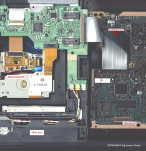
b) SCPH 30004
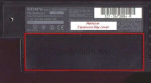
1. Remove the EXPANSION BAY cover and the warranty-void-sticker (don´ t need it any more 😉 )
Fig. 4: Expansion Bay
2. Remove the bottom and top cover by removing the screws under the small plastic/rubber
pads.(Sorry no pictures, yet)
3. Remove the screws holding the rfi-shield and the metal base plate first, then the shield and plate
Fig. 5: Cover sheets
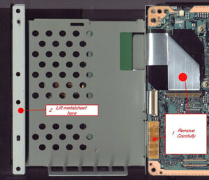
4. Unplug the silver ribbon cable (drive unit connector) and the Expansion Bay connector (Be very
careful !!!). Lift off the metalsheet on it´ s left side.
Fig. 6: disconnecting the drive
5. Turn the machine around (to top side) and dismount the drive by removing the two screws holding it.
Get the drive unit out of the console (make sure you´ ve disconnected it in step 4 !!!)
Fig. 7: cd/dvd drive top side
6. Turn the console again upside down. Lock the black isolation sheet in position with a small strip of
power-strip (Tesa) – this is important as the silver ribbon cable is conductive on its surface! Place the
drive upsidedown on the Expansion Bay spacers and the mainboard´ s left side. Reconnect the silver
ribbon cable.
Fig. 8: service mode setup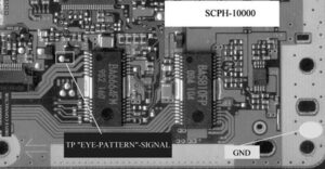
4.
Adjustment
Adjustment´s basically the same for all model types, only the the testpoints differ.
Connect your probe to the TP and GND. I soldered a small piece of wire to the pad and connected the
probe via the clamp, this is safe and replaces the ,,third hand” you would need to hold the probe while
adjusting the laser and holding the drive. Set your oscilloscope to 20mV/Sect. and 0.2us/Sect.
SCPH 10000
Fig. 9: SCPH-10000 (Jap) test pin
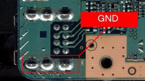
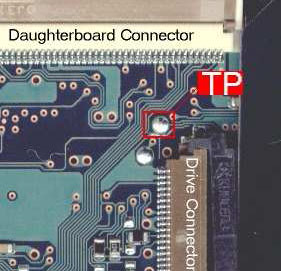
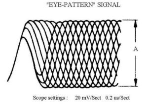
Fig. 10: SCPH-30004 (Eur) test pin
SCPH 30004
Performing the adjustments
Power up the PS2 and insert the PS2 utility disc.
You should now see the ,,eye-pattern” signal (as below) on your scope. Wait until the disc is
completely booted to get a stable picture on your scope.
Fig. 11: perfect test signal
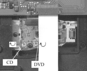
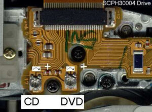
Turn the resistor marked `CD` clockwise until you get the maximum undistorted ,,eye-pattern”
(if you want more safety and a longer life of your laser then turn back a bit so the laser doesn´t
run at full power).
SCPH 10000
SCPH 30004
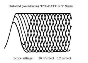
If you get a distorted signal just turn back a bit until it becomes stable and clear !
Fig. 12: distortet test signal (see the flattened top !)
Ok, now the CD section is adjusted so replace the utility/demo CD with the DVD and reset the console.
Now do the same adjustments as above but use the variable resistor marked ` DVD` this time.
Safe values (tested on Jap model only!) :
Mode
DVD
CD
Oscilloscope setting
20mV / 0.2us
20mV / 0.2us
per Section
per Section
,,Eye-Pattern” signals´ amplitude (A) set to
800mV Vpp
640 mV Vpp
5.
Replacing the Laserunit
1. Disassemble the PS2 as described above.
2. Disconnect the silver ribbon cable from the drive (at the mainboard´ s connector),
dismount the driveunit by removing the 2 screws holding it
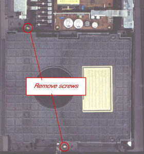
3. Remove the cover of the drive (4 screws) using the precision screwdriver
4. Turn the drive-unit upside-down
5. Disconnect the laser-unit connector (be careful – the ribbon cable is very sensitive !!)
Fig. 13: laserunit connectors
6. Push the white slider to the left in order to release the drawer
Fig. 14: tray lock slider
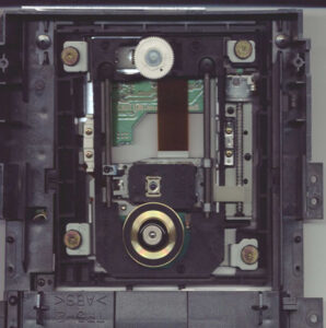
7. Pull out the drawer / tray completely
Fig. 15: drawer / tray bottom side
8. Turn around the drive again
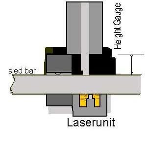
9. Now´ s the tricky part:
Measure the height of the laserunit at the marked point using the precision height gauge.
Write down the measured value, this will be important later on !!!
10.Remove the marked screws, use the TORX screwdriver for the small screw adjusting the lu´ s height
11.Remove the laserunit by (carefully) pulling out the slider bars
12.Mount the white, plastic steering plate and the TORX screw to your new laserunit (sorry no picture,
yet!)
13.Reassemble the drive the reverse way.
14.Adjust the height of the laserunit to the drive you measured in (9)
15.Desolder the anti-statics protection pins (just remove the solder) on the lu´ s pcb
16.Remount the drive unit and reconnect it to the mainboard.
17.Adjust the laserunit electrically according to the adjustments-section
18.Reassemble your PS2 and have fun !!!
PS2 Disassembly Instructions
Slim PS2 Disassembly:
http://www.modchipstore.com/support/downloads/ps2slim-disassembly.gif
THIS LINK TELLS YOU HOW TO CORRECTLY TAKE APART YOUR PS2 CONSOLE SYSTEM
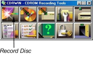
Copying PS or PS2 games using CDRWIN (You can also use newer software like Nero, CD Copy and other Burning programs)
A demo copy of CDRWIN 4.0a beta can be downloaded by clicking here. To purchase the full version of CDRWIN please visit GoldenHawk Technologies’ website.
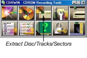
1. Open/run the CDRWIN program.
2. From the CDRWIN main interface menu click on the ‘extract disc’ button.
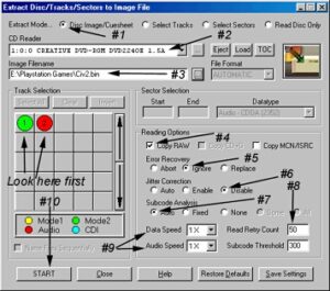
3. Select the ‘disc image/cuesheet’ radio button (1).
4. Enter the path location of the where you would like the image file created and stored. Input an image file name and remember to ensure that the file has a .bin extension. Name the file appropriately ensuring you do not use spaces and the name is under eight characters. (2)
5. Set to ‘copy raw’ for all PlayStation games (4).
6. Set the ‘error recovery’ button to ‘ignore’ (5).
7. Disable ‘jitter correction’ (6).
The table of contents on the disc determines how to configure the setup of CDRWIN. If, in the table of contents box, you observe either a) one Mode 2 Track or b) one Mode 2 Track and one Audio Track, set ‘subcode analysis’ to ‘auto’. If multiple audio tracks appear, set the ‘subcode analysis’ to ‘fixed’.
8. Set ‘read retry count’ to a number of at least 50.
9. Set the ‘data and audio’ speeds to ‘1X’ or ‘2X’ for best results.
10. Click on the ‘start’ button and the copying process will begin.
11. Once the disc has successfully extracted return to the main CDRWIN menu and click on the ‘record disc’ button.
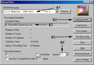
12. Select your CD-Writer form the pull down menu.
13. Click the ‘load cuesheet’ button. Select your created image file and choose the *.cue file that was automatically created in the extraction process.
14. Double-check that the proper *.cue file was selected. Its name will appear in this field.
Set recording speed to ‘1X’ for best results.
15. Click on the ‘start recording’ button to begin the recording process.
Finding out your PS2 version:
Please go to :
http://www.modchipstore.com/customer/pages.php?pageid=34
Thanks
Hi, the V12 Laser Fix is available here at: It is rec. for EVERY version 12 PS2 to get this unit installed.
PS2 V12 Laser Fix PCB For Slim Line Console!
See details PS2 V12 Laser Fix PCB For Slim Line Console!
When you modify a slimline PS2 (v12) then you must add this small pcb which limits the current to the coils of the laser. It happens very often that the v12 Laser completely burns up after just one or two hours of gameplay. By adding this fix you can feel yoursef on the safe side after modding th…
You will only need two tools to take apart the Wii. The first is a small Phillips screw driver, which should be easy to locate. The second tool you will need is a Triwing driver. This type of driver is not very common and might take some phone calls or internet searches to locate. Ours was purchased off of Ebay several months ago to repair a broken Gameboy.
To disassemble:
NOTE
Hiding screws under stickers and rubber pads is a common method used by electronics manufactures to help increase the aesthetics of their devices, as well as prevent people from easily locating screws and taking apart their products.
3. Unscrew the two Triwing screws and three Phillips screws from the bottom of the Wii.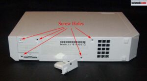
Figure 3
4. Bottom Screws
5. Flip the Wii over onto its right side. Locate and remove the two rear rubber feet and the two rectangle stickers near the faceplate.
6. Remove the two silver Triwing screws in the holes and remove the two black Triwing screws on the faceplate (Figure 4)
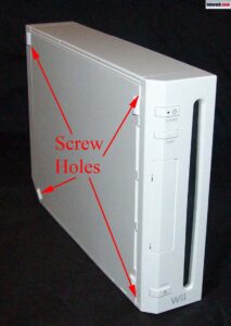
Figure 4
Left side screw locations
7. Flip the Wii upright and carefully remove the two socket covers. They come right out with a little wiggling.
8. Remove the three black Phillips screws from the black plate (Figure 5). Note the one closest to the faceplate is the longest and will need to go back into that hole when putting the Wii back together.
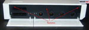
Figure 5
Top black plate screw locations
9. With the screws removed, carefully pull off the faceplate of the front of the Wii. You will need to disconnect the red/black wire plug from the Wii to remove the faceplate completely. Figure 6 shows what is hiding under the faceplate.
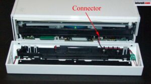
Figure 6
Under the Wii faceplate
10. Remove black plate from memory/controller socket area.
11. Remove two silver Phillips and two silver Triwing screws from memory/controller socket area (Figure 7).
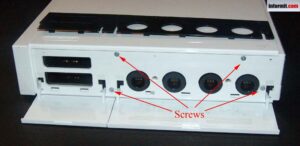
Figure 7
Topside screw locations
g
12. Lay the Wii on left side (with the ATI and Nintendo logo facing you) and slowly work the right side cover of the console off the device. This will take a little bit of force. If something appears to be stuck, double check to ensure you removed all the screws.
13. Locate and remove four screws holding DVD reader in place. Two are located in plain site in the middle of the unit. Two are located near the front of the Wii inside the DVD unit (Figure 8).
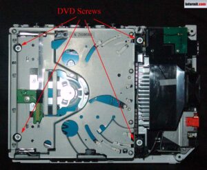
Figure 8
The insides of the Wii
14. Slowly tilt the DVD player upward toward top of Wii. There are two wires that need to be disconnected before you can safely remove the DVD unit. One is a plug type of connector that only requires a little tug. The other is a circuit strip connector that requires you to lift the brown catch, which will release the pressure holding the strip in place (Figure 9). Do not break this!
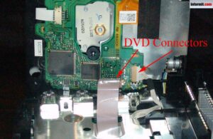
Figure 9
15. You can then access the Installation Canvas and proceed with your Wii Modification
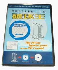
This is the Breaker Pro Product Page:
See details
http://www.modchipstore.com/customer/product.php?productid=16172&cat=108&page=1
This page has full details on usage for the Breaker Pro. You can also see detailed step by step instructions with pics here at:
http://www.modchipstore.com/customer/pages.php?pageid=115
Thanks!
PlayStation Boot Disc User Manual:
Before using the PlayStation Boot Disc, please install the relevant components to your console according to the installation diagrams show below. Then follow the steps outlined in this manual to play your favorite games. Using the PlayStation Boot Disc to Play Import Games
Switch off Your PS Console
Insert the PlayStation Boot Disc
Switch on your PS Console. After a few seconds, and you will see the following words on the screen ” Please Insert Game Disc “
Remove the PlayStation Boot Disc
Insert the Import game you wish to play. You can either close the console lid or leave it open
Press the O button and the game will now start to load
For PSOne Users: Component Needed: PVC Card (provided)
This PVC Card is only for the new small white mini Playstation Machines that say PSOne on them
Peel Off The Cover From The PVC Card
Don’t release the “OPEN” button until you slip
the small end of the PVC Card into Slot A.
Press the “OPEN” button & you will see Slot A
– Place the adhesive side of the PVC Card properly
# NOTE: The PVC card can be left on the console for good once it is installed.
For PlayStation Users: Component Needed: Spring (provided)
This Spring is only for the older LARGER Grey color Playstation Machines and NOT for the small white mini PSOne Console
– Open the lid of your console
– Place the bottom metal part of the spring into the circular know.
– Fix the head of the spring into the pointed rod.
# Note: With the special elastic design of our spring, you can still open
and close your console lid freely after the spring is installed.
Anti-Modchip Games
Some import games are protected against an import device called a “Mod Chip”. These devices are installed in many playstation machines to allow a user to play import games. When playing an original game the user will be presented with a screen saying that the playstation has been modified and the game can not continue. The Playstation Boot-Disc has a facility to allow you to play those original games and even enter cheat codes that are for the Game Shark(tm) and other cheat devices. Simply put, you can play all anti-modchip games and even use all your favorite gameshark(tm) codes for more lives, health, ammo, etc..
First you will need your cheat codes or anti-mod codes, how to obtain these is detailed later. Insert the The Playstation Boot-Disc and boot as normal. When the screen appears that asks you to “Please Insert Import Disk and Press Start” press the “SELECT” button on the Joypad. This will take you to a screen full of blank codes. Enter each code in turn as it appears on the web site or magazine. Use the direction pad and the O and X buttons to enter the code. Each game will have its own different cheat codes/anti-mod codes, pay particular attention to the origin of the game. I.E. Japanese game will have different codes than the USA version of that game with the same name, however, the Japanese code will not work on the USA version of the game and vice-versa. If you enter the wrong codes do not worry it will not do any harm, but the game may not run and may even crash if the wrong codes are entered.
You can enter up to 30 codes. If you need to enter more than 6 codes then moving the cursor down past the 6th line will scroll the screen up one line. Once you go past the 30th code the cursor will go back to the first code. Pressing select at any time will toggle between the “Please Insert Import Game And Press Start” screen and the codes screen. Codes will remain unchanged when you do this.
Websites containing cheat codes and anti-modchips code: http://www.megagames.com/psx
Most of the recent released PSX games are protected and are able to detect if a mod chip or mod cd has been installed. When it finds one it will show the picture below and it stops playing the game.
PlayStation Boot Disc User Manual:
Before using the PlayStation Boot Disc, please install the relevant components to your console according to the installation diagrams show below. Then follow the steps outlined in this manual to play your favorite games. Using the PlayStation Boot Disc to Play Import Games
Switch off Your PS Console
Insert the PlayStation Boot Disc
Switch on your PS Console. After a few seconds, and you will see the following words on the screen ” Please Insert Game Disc “
Remove the PlayStation Boot Disc
Insert the Import game you wish to play. You can either close the console lid or leave it open
Press the O button and the game will now start to load
For PSOne Users: Component Needed: PVC Card (provided)
This PVC Card is only for the new small white mini Playstation Machines that say PSOne on them
Peel Off The Cover From The PVC Card
Don’t release the “OPEN” button until you slip
the small end of the PVC Card into Slot A.
Press the “OPEN” button & you will see Slot A
– Place the adhesive side of the PVC Card properly
# NOTE: The PVC card can be left on the console for good once it is installed.
For PlayStation Users: Component Needed: Spring (provided)
This Spring is only for the older LARGER Grey color Playstation Machines and NOT for the small white mini PSOne Console
– Open the lid of your console
– Place the bottom metal part of the spring into the circular know.
– Fix the head of the spring into the pointed rod.
# Note: With the special elastic design of our spring, you can still open
and close your console lid freely after the spring is installed.
Anti-Modchip Games
Some import games are protected against an import device called a “Mod Chip”. These devices are installed in many PlayStation machines to allow a user to play import games. When playing an original game the user will be presented with a screen saying that the PlayStation has been modified and the game can not continue. The Playstation Boot-Disc has a facility to allow you to play those original games and even enter cheat codes that are for the Game Shark(tm) and other cheat devices. Simply put, you can play all anti-modchip games and even use all your favorite Gameshark(tm) codes for more lives, health, ammo, etc.
First, you will need your cheat codes or anti-mod codes, how to obtain these are detailed later. Insert The Playstation Boot-Disc and boot as normal. When the screen appears that asks you to “Please Insert Import Disk and Press Start” press the “SELECT” button on the Joypad. This will take you to a screen full of blank codes. Enter each code in turn as it appears on the website or magazine. Use the direction pad and the O and X buttons to enter the code. Each game will have its different cheat codes/anti-mod codes, pay particular attention to the origin of the game. I.E. Japanese game will have different codes than the USA version of that game with the same name, however, the Japanese code will not work on the USA version of the game and vice-versa. If you enter the wrong codes do not worry it will not do any harm, but the game may not run and may even crash if the wrong codes are entered.
You can enter up to 30 codes. If you need to enter more than 6 codes then moving the cursor down past the 6th line will scroll the screen up one line. Once you go past the 30th code the cursor will go back to the first code. Pressing select at any time will toggle between the “Please Insert Import Game And Press Start” screen and the codes screen. Codes will remain unchanged when you do this.
Websites containing cheat codes and anti-modchips code: http://www.megagames.com/psx
Most of the recently released PSX games are protected and can detect if a modchip or mod cd has been installed. When it finds one it will show the picture below and it stops playing the game.
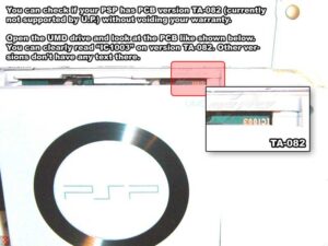
How to detect if your PSP motherboard is TA-082 without voiding your warranty. Simply by looking inside your UMD Drive you can make sure that the U.P. is compatible with your PSP console. The Undiluted Platinum PSP Mod Chip is not compatible with Motherboard TA-082 as of yet. If you check your PSP, and it has Matches the image below, then you have version TA-082. If that is the case, then please wait for a future release of the chip that will be compatible with your PSP, or installation diagrams compatible with that motherboard version.
Steps to install the Undiluted Platinum on your PSP
The Undiluted Platinum is available here.
The Undiluted Platinum installation packages are available here.
The Undiluted Platinum Premodified PSP is available here.
Precautions
1. Installation of the Undiluted Platinum is ONLY for skilled professionals. Attempting to install this product without thorough knowledge could damage the system, chip, and possibly the installer.
2. The most difficult and dangerous part of the installation is the removal of the solder mask. Please be patient.
3. The PSP motherboard contains highly condensed traces. A video aid such as a microscope is encouraged and even needed in the installation process.
Before Starting
Before installing the U.P. on your Playstation Portable, you need to figure out if you have the right version of PSP. Most of the PSPs can be modded, there is only one version currently out that cannot. It is the TA-082 and it is mainly in Japan. We have found a way to check and see if you have that motherboard without having to disassemble your system. Click here for instructions on finding out if you have a TA-082 PSP.
After you have made sure that you don’t have the TA-082 PSP you can proceed to disassemble your PSP.
Once you have finished disassembling the PSP you are now ready to begin the tedious installation process. Take your time and follow these diagrams for their respective boards.
Official Undiluted Platinum Diagrams
TA-081 Motherboard Click Here
TA-081 Motherboard Click Here
Also, you can check here for the official installation instructions from Undiluted Platinum.
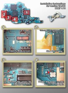
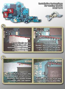
Installation
1. The stencils are used to assist with the process of removing the solder mask from the motherboard PCB. This is done by first fixing the stencil in place (as shown by the installation diagrams) and then scratching the solder mask off the PCB with a sharp tool using the edge of the stencil as a guide. This is the most hazardous part of the installation since it is possible to cause permanent damage to the PCB traces during this procedure. Great care must be taken not to apply too much pressure whilst removing the solder mask, otherwise, the traces can be damaged or even severed. Secure the stencil in place with hot glue. First position the stencil, then apply hot glue to hold it in place temporarily. Take care not to place glue over any surface mount components otherwise they may be damaged when the glue is removed.
2. Using a sharp tool such as a utility knife and the stencil as a guide, cut the PCB trace as indicated by the yellow spot on the installation diagram. Take care not to damage any of the adjacent traces! To verify that the trace has been severed perform a continuity test between points P and J as shown in the installation diagram. If the PCB trace has been severed the continuity test should fail.
3. Once the solder mask has been removed and the trace cut carefully removes the hot glue and then the stencil.
4. Affix the FPC cable in place (as shown by the installation diagrams) using glue or double-sided tape.
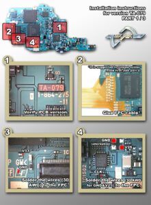
Here are the installation diagrams for the Undiluted Platinum PSP modchip for motherboard TA-079
To Install follow the directions closely and make sure to use the proper soldering technique and care. Please do not attempt to install if you do not know how to solder, and have a professional do it. We also offer Professional Installation Services.
Image 1/3: (click image to enlarge)
Here are the installation diagrams for the Undiluted Platinum PSP modchip for motherboard TA-081
To Install follow the directions closely and make sure to use the proper soldering technique and care. Please do not attempt to install if you do not know how to solder, and have a professional do it. We also offer Professional Installation Services.
Image 1/3: (click image to enlarge)